|
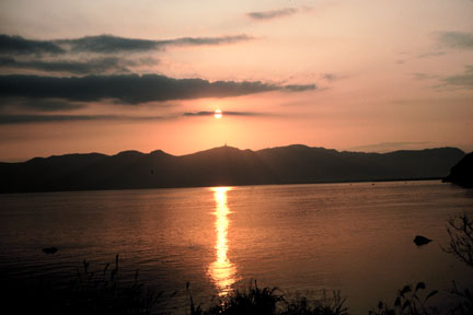
Glittering Light on Water Joseph A. Shaw On a November evening in 1982 I was on a train slowly wandering around the edge of a bay in southern Japan. The setting sun created a magical streak of glittering light reaching across the water (Figure 1). Even though I had no formal optics training at that time, I took special care to photograph this optical treat, even thinking that someday I would like to understand this glittering light better. I knew, at least, that this would be a nice addition to the slide show I would share with my family and friends back home when telling them about Japan - the "Land of the Rising Sun" (or setting sun in this case).
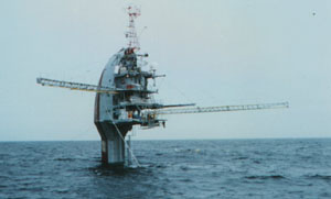
Thirteen years later I was on an inverted ship in the Pacific Ocean (Figure 2) measuring glitter patterns created with a laser. With the passage of time, I have discovered that understanding how glitter patterns are formed, and even forming my own glitter patterns to measure sea-surface roughness, helps me enjoy nature's glitter even more.
How glitter patterns are formed The name "glitter pattern" implies a moving and changing phenomenon. Glitter patterns consist of many bright points of light that come and go, blending together to form a smooth path of glittering light when viewed at a distance. If you look closely at a glitter pattern, you can see individual points of light. Each of these points of light is a specular reflection of the sun, called a sun glint. Glints occur on the water where the local slope provides a direct specular reflection of the sun. A perfectly smooth surface would contain only one glint. It is this kind of glass-smooth surface that produces the nearly perfect images we see in nature calendars of mountains reflected in a lake. But if the water surface is rippled by even the slightest wind, reflected images become wrinkled and indistinct. A light source, such as the sun or moon, or even a streetlight or distant illuminated window, is then reflected from multiple spots on the surface (Figure 3). As the wind-rippled surface moves, so do individual glints. But the ensemble of glints produces a glitter pattern whose shape and size can be related to the roughness of the water and the viewing geometry.
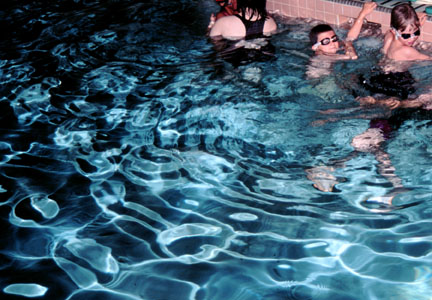
Glitter patterns are roughly elliptical, with an aspect ratio that depends on the source elevation angle.1,2 For example, the sun produces a circular glitter pattern when it is directly overhead (90 elevation angle) and produces an elongated elliptical pattern near sunset or sunrise (small elevation angle). This all assumes a uniformly rough surface; quite often, however, wind gusts increase the roughness or surface slicks reduce the roughness in a localized region. These kinds of effects are evident in Figure 1, especially close to the near shore where the glitter pattern is much wider than elsewhere (perhaps partly because of the wind generated by the passing train). For a high light source, the angular length of a glitter pattern is equal to four times the angle of the maximum wave slope (figure 3). Waves inclined both toward and away from the observer create glints, resulting in a factor of two times the maximum wave slope; the additional factor of two is a result of angular doubling on reflection. The ratio of the glitter-pattern width to its length is given by the sine of the source elevation angle. If the light source is at the same elevation as the observer, the glitter pattern dimensions are half as large as with an infinitely high source, but the width-to-length ratio is the same. As the sun or moon drops lower in the sky, the glitter pattern gets progressively narrower until the width-to-length ratio reaches a minimum when the source elevation angle is twice the maximum wave slope. Beyond this angle, as the sun or moon approaches the horizon, the glitter pattern becomes shorter because of shadowing and eventually disappears. Glitter patterns on water are similar to vertical light pillars in the sky, caused by reflection from ice crystals floating or falling with a distribution of slopes.1-5 Growing up in Alaska, I often saw light pillars above city lights during the winter when the ice-laden atmosphere was calm and cold. But sun pillars can be seen even in more temperate climates, especially near sunrise or sunset in the vicinity of thin cirrus clouds. Better weather forecasts from glitter patterns Have you ever been rained on during an afternoon forecast as "mostly sunny?" This kind of event could happen less often with improved knowledge of the wind speed and direction over the ocean three or four days earlier. Satellite sensors can see large regions of ocean where there are no people to measure winds, but they rely on models to infer wind speed and direction from surface roughness. It turns out that much of the information relating surface roughness to the wind came from studying patterns of light glittering on the ocean surface. Recall that the maximum wave slope can be determined from the geometry of glitter patterns. In 1951, Charles Cox and Walter Munk found a more quantitative way of using glitter patterns to derive a statistical model for the complete wave-slope distribution.6,7 They used cameras in the bomb bay of a World War II surplus B-17G aircraft to photograph sun glitter on the Pacific Ocean near Hawaii.6,7 By relating the photographic density to the probability of a sun-glint wave slope, Cox and Munk derived a wave-slope probability density function (pdf). The photographs used to derive this model actually were recorded with the camera lenses removed, resulting in a blob of light with continuously decaying brightness at the edges. This experiment was limited to measuring slopes smaller than about 28 because the light from larger slopes, which occur with lower probability, was lost in the background. By examining multiple images in this way at different wind speeds, Cox and Munk were able to show that the pdf for ocean wave slopes can be described as a Gaussian plus higher-order skewness and kurtosis terms. The actual pdf tends to have higher probability for very small and very large slopes than a Gaussian distribution. Furthermore, the along-wind distribution is skewed, showing a higher probability for downwind slopes than for upwind slopes. This makes sense because the wind pushing the small wind waves causes them to lean downwind. The pdf variance (mean-square slope) increases approximately linearly with wind speed, indicating that the surface gets steadily rougher as the wind blows harder. Forty-four years after Cox and Munk flew their B-17G over the Hawaiian Islands, my colleagues and I set out to examine the ocean wave-slope probability model in more detail.8,9 This time, however, we used laser-glitter patterns to avoid the explicit dependence on solar angle and sky conditions. In September 1995, we measured laser-glint patterns from the ship shown in Figure 2 about 20 km off the Oregon Coast in the Pacific Ocean. By counting the number of glints in angular bins as a narrow laser beam was scanned repeatedly over the ocean surface, we derived wave-slope probability density functions that agreed well with the Cox and Munk model under similar conditions. We also found, however, that the surface roughness depends on the air-sea temperature difference (which was nearly zero in the Cox-Munk experiment).8 At a given wind speed, water warmer than the adjacent air leads to a rougher surface than predicted by the Cox & Munk model and water colder than air results in a smoother surface. Therefore, the wind cannot be determined uniquely from the surface roughness alone. We also used video cameras to record images of the surface illuminated by a wide cone of laser light. The image at the top of Figure 4 is a laser-glint pattern seen by a video camera looking straight down at a smooth ocean surface (1 m/s wind speed). Nine successive video frames have been averaged to provide a 0.3 second integration time, resulting in an image similar to what would be seen by a human observer. Large closed loops are formed by glints moving in pairs around waves of finite length and width as the surface undulates. Similar loops can be seen in the reflection of overhead street lights or the moon from water, or, as shown on the bottom of Figure 4, in the reflection of a camera flash from the water in a swimming pool.1,2 To see such loops, the surface must be smooth enough that the wave crests are large and slowly varying. When the surface roughness increases, the loops become smaller and change rapidly. In fact, we found that a time series of the number of bright regions in these glint images is a fractal process whose fractal dimension varies with surface roughness.9 So, in addition to being beautiful and fun to watch (especially in motion), these light loops also convey quantitative information about the surface and its environment.
Where glitter paths lead You do not have to be a remote sensing expert to appreciate glitter patterns. From sidewalk puddles to the ocean, beautiful light shows can be seen by anyone with the attention to notice. Depending on the amount of patience you have for such things, you can either casually notice these patterns or spend hours examining them in detail. Either way, there is much to be learned and much to be appreciated about nature by watching light glittering on water. References 1. M.G.J. Minnaert, Light and Color in the Outdoors, Translated and Revised by L. Seymour, Springer-Verlag, New York, 1993. 2. D.K. Lynch and W. Livingston, Color and Light in Nature, Cambridge Univ. Press, 1995. 3. R. Greenler, Rainbows, Halos, and Glories, Cambridge Univ. Press, 1980. 4. A.J. Mallman et al., "Comparison of Sun pillars with light pillars from nearby light sources," Appl. Opt. 37, 1441-1449, 1998. 5. W. Tape, Atmospheric Halos, American Geophysical Union, Wash., D.C., 1994. 6. C. Cox and W. Munk, "Statistics of the sea surface derived from sun glitter," J. Marine Res. 13, 198-227, 1954. 7. C. Cox and W. Munk, "Measurement of the roughness of the sea surface from photographs of the Sun's glitter," J. Opt. Soc. Am. 44, 838-850, 1954. 8. J.A. Shaw and J.H. Churnside, "Scanning-laser glint measurements of sea-surface slope statistics," Appl. Opt. 36, 4202-4213, 1997. 9. J.A. Shaw and J.H. Churnside, "Fractal laser glints from the ocean surface," J. Opt. Soc. Am.-A 14, 1144-1150, 1997. |
|||||