|
|
A block diagram of FLOE (Fish Lidar, Oceanic, Experimental).
|
FLOE Hardware
In this Fish Lidar System, a laser emits a short
pulse (~15ns) of green (532nm) light toward the ocean surface. Some
of the light is reflected from the surface and some continues down to be
reflected back from a school of fish. A 20-cm telescope is
pointed in the same direction as the laser and collects the reflected light.
This telescope is a simple refractor that uses a condensor lens.
A 10-nm wide interference filter filters out most of the background light
and lets only the laser light through to the photomultiplier tube.
The photomultiplier tube (PMT) detects the reflected laser light
and converts it into an electrical signal. In some cases, a logarithmic
amplifier compresses the electrical signal. The signal is routed
to an analog-to-digital converter (ADC) in a personal computer where it
is digitized and saved to the hard disk. In other cases, two ADC
boards with different gains are used to increase the dynamic range of the
receiver.
Two different displays are available on the aircraft
computer. The first is a line plot of the return signal as a function
of time for each shot. Since time can be related to distance through
the speed of light, this is equivalent to a plot of the return energy as
a function of depth for each laser pulse. At 30 pulses per second,
this display produces 30 plots per second, which can be hard to follow.
Therefore, we have another display that shows depth in the vertical axis,
shot number in the horizontal axis, and encodes return power as a gray
level. This is similar to the display in a conventional echo sounder.
Fish schools show up a regions of more return power. We have the
option to identify the surface in each shot and relate the vertical axis
to actual depth. Another option is to estimate the background water
return and subtract it from each shot to make fish schools easier to see.
|
|

|
|
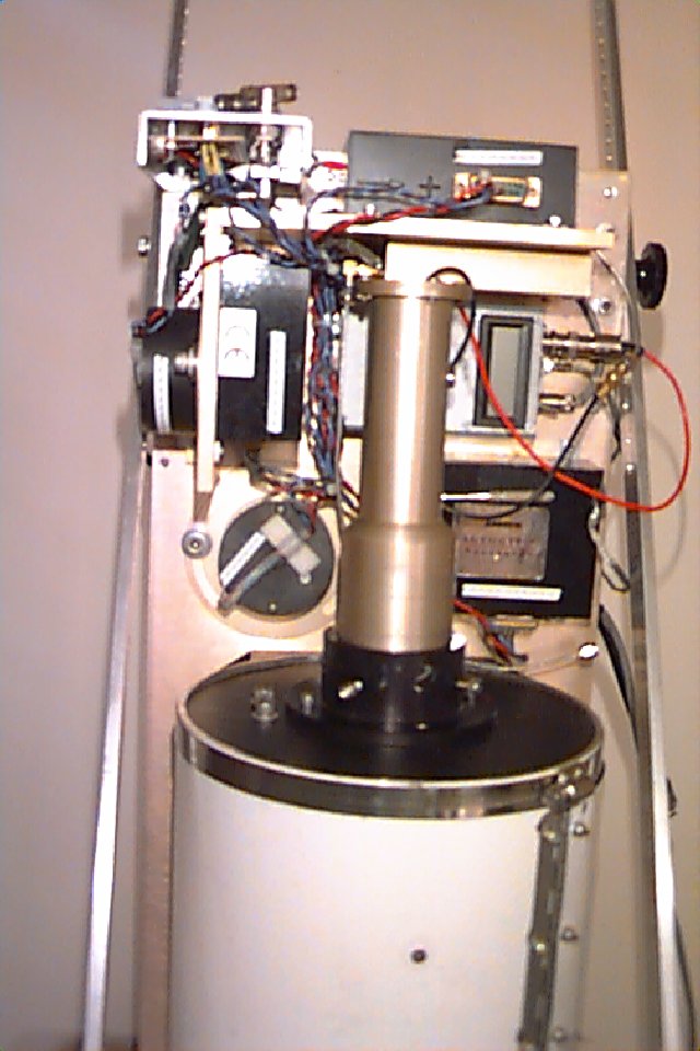
Optics Package
|
Detector
|
Electronics Rack
|
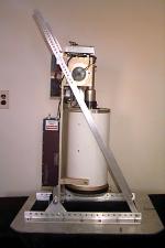
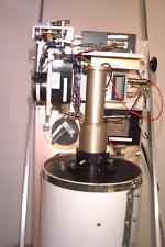
The photo on the left shows the
optics package. This is the part that mounts over the port in the
aircraft. A different mounting plate is made to fit each plane.
The black box on the left is the laser. The white tube on the right
is the telescope. Both of these are mounted to the main supporting
plate that is fixed to the base plate in such a way that the incidence
angle of the lidar can be adjusted. At the top of the telescope are
the detector housing and the instruments to measure aricraft attitude.
These are shown more clearly in the center photo, which was taken from
the telescope side of the optics package. The photo on the right
is the electronics rack as it was used in the King Air. The touch-screen
computer monitor is on the top; next is the digital delay generator used
to control the timing between the laser pulse and the digitizer; next is
the computer; next is the laser power supply; on the bottom is the laser
cooling unit. Photos of the lidar installed on the various airplanes
are on the pages for the
Partenavia
Observer , Beechcraft
King Air , Casa ,
and Cessna Cardinal .
Specifications
| TRANSMITTER |
|---|
| Wavelength |
532 nm |
| Pulse length |
15 nsec |
| Pulse energy |
100 mJ |
| Pulse repetition rate |
30 Hz |
| Beam divergence |
62 mrad |
| RECEIVER |
|---|
| Aperture diameter |
17 cm |
| Field of view |
63 mrad |
| Optical bandwidth |
10 nm |
| Electronic bandwidth |
100 MHz |
| Sample rate |
1 GHz |
| Polarization |
orthogonal |
An intensified CCD camera has also been used with the system for some applications.
This camera has a very short exposure time (20 ns) that can be triggered to take a picture
when the laser pulse is at a preselected distance below the surface of the water. The
picture that results is an image of the laser spot scattered by particles in the water at that
depth. If there is a large fish or other object above the illuminated particles, its shadow
will show up in the image. This camera has been used to detect
salmon and
floating debris.
|